- 您现在的位置:买卖IC网 > Sheet目录350 > PCA9922PW,118 (NXP Semiconductors)IC LED DRIVER LINEAR 16-TSSOP
NXP Semiconductors
PCA9922
8-channel constant current LED driver with output error detection
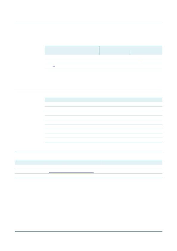
17.4 Package related soldering information
Table 13.
Package
Suitability of through-hole mount IC packages for dipping and wave soldering
Soldering method
Dipping
Wave
CPGA, HCPGA
DBS, DIP, HDIP, RDBS, SDIP, SIL
PMFP [2]
-
suitable
-
suitable
suitable [1]
not suitable
[1]
[2]
For SDIP packages, the longitudinal axis must be parallel to the transport direction of the printed-circuit
board.
For PMFP packages hot bar soldering or manual soldering is suitable.
18. Abbreviations
Table 14.
Acronym
CDM
EMI
ESD
HBM
LED
MM
MSB
PCB
PWM
19. Revision history
Abbreviations
Description
Charged-Device Model
ElectroMagnetic Interference
ElectroStatic Discharge
Human Body Model
Light Emitting Diode
Machine Model
Most Significant Bit
Printed-Circuit Board
Pulse Width Modulator
Table 15.
Revision history
Document ID
PCA9922 v.2
Release date
20110406
Data sheet status
Product data sheet
Change notice
-
Supersedes
PCA9922 v.1
Modifications:
?
Figure 1 “ Block diagram of PCA9922 ” : removed block “auto shutdown and auto power-up”
PCA9922 v.1
20090115
Product data sheet
-
-
PCA9922
Product data sheet
All information provided in this document is subject to legal disclaimers.
Rev. 2 — 6 April 2011
? NXP B.V. 2011. All rights reserved.
24 of 27
发布紧急采购,3分钟左右您将得到回复。
相关PDF资料
PCA9955TW,118
IC LED DRVR CONST CURR
PCF85102C-2P/03,11
IC EEPROM 2KBIT 100KHZ 8DIP
PCF85103C-2T/00,11
IC EEPROM 2KBIT 100KHZ 8SOIC
PCF8570T/F5,512
IC SRAM 2KBIT 100KHZ 8SOIC
PCF8582C-2T/03,118
IC EEPROM 2KBIT 100KHZ 8SOIC
PCF8594C-2T/02,118
IC EEPROM 4KBIT 100KHZ 8SOIC
PCF8598C-2P/02,112
IC EEPROM 8KBIT 100KHZ 8DIP
PCU9955TW,118
IC LED DRVR CONST CURR
相关代理商/技术参数
PCA9922PW118
制造商:NXP 功能描述: 制造商:NXP Semiconductors 功能描述:
PCA9952TW,118
功能描述:LED照明驱动器 16-ch Fm+ I2C-bus 57 mA LED driver
RoHS:否 制造商:STMicroelectronics 输入电压:11.5 V to 23 V 工作频率: 最大电源电流:1.7 mA 输出电流: 最大工作温度: 安装风格:SMD/SMT 封装 / 箱体:SO-16N
PCA9952TW/Q900,118
制造商:NXP Semiconductors 功能描述: 制造商:NXP Semiconductors 功能描述:IC LED DVR 16CH I2C CC 28HTSSOP 制造商:NXP Semiconductors 功能描述:LED Lighting Drivers 16-channel Fm+ I2C- bus 57 mA LED driver
PCA9955ATW/Q900J
功能描述:LED 驱动器 IC 16 输出 线性 I2C 调光 57mA 28-HTSSOP 制造商:nxp semiconductors 系列:汽车级,AEC-Q100 包装:剪切带(CT) 零件状态:过期 类型:线性 拓扑:- 内部开关:是 输出数:16 电压 - 供电(最低):3V 电压 -?供电(最高):5.5V 电压 - 输出:20V 电流 - 输出/通道:57mA 频率:8MHz 调光:I2C 应用:背光 工作温度:-40°C ~ 85°C(TA) 安装类型:表面贴装 封装/外壳:28-SOIC(0.173",4.40mm 宽)裸露焊盘 供应商器件封装:28-HTSSOP 标准包装:1
PCA9955ATWJ
功能描述:LED 驱动器 IC 16 输出 线性 I2C 调光 57mA 28-HTSSOP 制造商:nxp semiconductors 系列:- 包装:剪切带(CT) 零件状态:过期 类型:线性 拓扑:- 内部开关:是 输出数:16 电压 - 供电(最低):3V 电压 -?供电(最高):5.5V 电压 - 输出:20V 电流 - 输出/通道:57mA 频率:8MHz 调光:I2C 应用:背光 工作温度:-40°C ~ 85°C(TA) 安装类型:表面贴装 封装/外壳:28-SOIC(0.173",4.40mm 宽)裸露焊盘 供应商器件封装:28-HTSSOP 标准包装:1
PCA9955BTW/Q900J
功能描述:LED 驱动器 IC 16 输出 线性 65mA 28-HTSSOP 制造商:nxp semiconductors 系列:- 包装:剪切带(CT) 零件状态:有效 类型:线性 拓扑:- 内部开关:是 输出数:16 电压 - 供电(最低):3V 电压 -?供电(最高):5.5V 电压 - 输出:- 电流 - 输出/通道:65mA 频率:- 调光:- 应用:汽车级,背光 工作温度:-40°C ~ 85°C(TA) 安装类型:表面贴装 封装/外壳:28-SOIC(0.173",4.40mm 宽)裸露焊盘 供应商器件封装:28-HTSSOP 标准包装:1
PCA9955BTWJ
功能描述:LED 驱动器 IC 16 输出 线性 65mA 28-HTSSOP 制造商:nxp semiconductors 系列:- 包装:剪切带(CT) 零件状态:有效 类型:线性 拓扑:- 内部开关:是 输出数:16 电压 - 供电(最低):3V 电压 -?供电(最高):5.5V 电压 - 输出:- 电流 - 输出/通道:65mA 频率:- 调光:- 应用:背光 工作温度:-40°C ~ 85°C(TA) 安装类型:表面贴装 封装/外壳:28-SOIC(0.173",4.40mm 宽)裸露焊盘 供应商器件封装:28-HTSSOP 标准包装:1
PCA9955TW,118
功能描述:LED照明驱动器 16-ch Fm+ I2C-bus 57 mA LED driver
RoHS:否 制造商:STMicroelectronics 输入电压:11.5 V to 23 V 工作频率: 最大电源电流:1.7 mA 输出电流: 最大工作温度: 安装风格:SMD/SMT 封装 / 箱体:SO-16N
